Aircraft Extrusion Tolerance
Aircraft Dimension Extrusion Tolerances
Profile tolerances are a key considerations in designing extrusions. Aircraft Extrusion Company understand the mechanics of working with aluminum. For each part we manufacture, we consider wall thickness, profile circumscribing circle size, location of dimension on the profile and the type of profile. We are also able to match the tolerance specifications with the right extrusion press size. While the aluminum industry provides standard dimensional tolerance guidelines for extruded aluminum profiles, flatness and twist, contours, straightness.
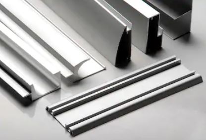
Table of Extrusion Tolerances
| Dimension | Tolerance in inches | Username | |
|---|---|---|---|
| Up Thru 0.124 | +/- 0.006 | Alloy 2000 and 7000 Series | |
| 0.125 - 0.249 | +/- 0.007 | Alloy 2000 and 7000 Series | |
| 0.250 - 0.499 | +/- 0.008 | Alloy 2000 and 7000 Series | |
| 0.500 - 0.749 | +/- 0.009 | Alloy 2000 and 7000 Series | |
| 0.750 - 0.999 | +/- 0.010 | Alloy 2000 and 7000 Series | |
| 1.000 - 1.499 | +/- 0.012 | Alloy 2000 and 7000 Series | |
| 1.500 - 1.999 | +/- 0.014 | Alloy 2000 and 7000 Series | |
| 2.000 x 3.999 | +/- 0.024 | Alloy 2000 and 7000 Series | |
| 4.000 - 5.999 | +/- 0.034 | Alloy 2000 and 7000 Series | |
| Corner and Fillet Radius | |||
| Sharp Corners | +/- 0.016 | Alloy 2000 and 7000 Series | |
| 0.016 - 0.187 | +/- 0.016 | Alloy 2000 and 7000 Series | |
| 0.188 and over | +/- 10% | Alloy 2000 and 7000 Series | |
We are proficient in SolidWorks and Autocad and cam translate engineering drawing and design.
We are proficient in SolidWorks and Autocad and cam translate engineering drawing and design.
About Tolerance
Profile tolerances are a key considerations in designing extrusions. Aircraft Extrusion Company understand the mechanics of working with aluminum. For each part we manufacture, we consider wall thickness, profile circumscribing circle size, location of dimension on the profile and the type of profile.